Wiring Diagram
What is a Wiring Diagram?
A wiring diagram is simply a pictorial representation of all the electrical connections in a specific circuit. The wiring diagram shows different components in a circuit via different shapes and symbols. These diagrams are an effective way of showing how wires are interconnected with different components in a system.
The Usage of Wiring Diagram
Wiring diagrams are mainly used when trying to show the connection system in a circuit. It is majorly used by building planners, architects, and electricians to present the wiring connections in a building, a room, or even a simple device. They can be accommodating when determining a fault in the connections, installing new wires and devices, locating electrical outlets, etc.
Wiring Diagram VS Schematic Diagram
Schematic diagrams are electrical layouts that mainly focus on the basic plan and function rather than its physical location. In contrast, the wiring diagram shows how wires are connected to a device and what will be their exact physical location in a circuit. Let's have a look at their differences with the help of a table.
| Features | Wiring Diagram | Schematic Diagram |
|---|---|---|
| Electrical Connections | Focuses on the connections between devices and elements in a circuit. | Focuses on the logical working of a circuit. |
| Symbols | It uses simplified shapes to represent the electrical components. | It uses abstract, graphic symbols to identify the components. |
| Lines | Lines represent the wiring in the circuit and between the components. | Lines represent the how the flow of the system and power output. |
| Purpose | To show the connection between components. | To show the electrical working of a circuit. |

4 Bit Counter Schematic (wikimedia)
Wiring Diagram and Pictorial Diagram
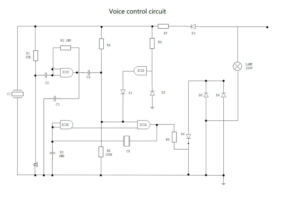
Among all the electrical wiring layouts, the pictorial diagram is the least productive one. These diagrams use photos along with highly-detailed drawings of the components to explain the wiring. For a layman, these drawings are useless. They can only be understood by someone with a strong knowledge of electrical components and wiring. In comparison to this, the wiring diagram is a simple one and can be easily understood.
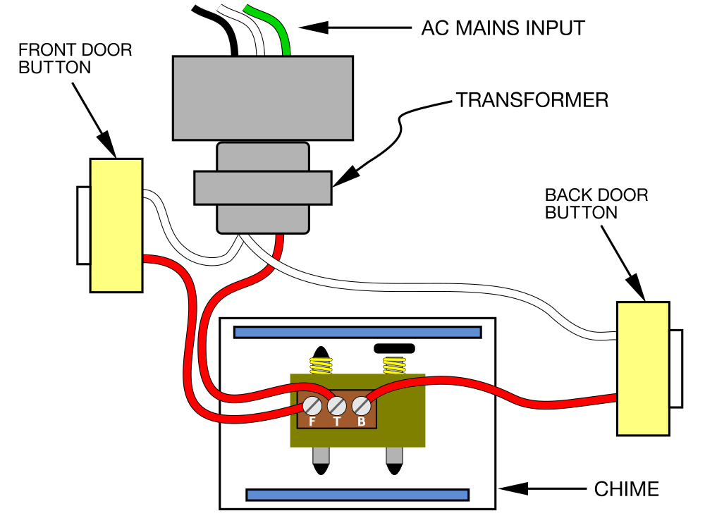
Doorbell Wiring Pictorial Diagram (wikimedia)
Standard Wiring Diagram Symbols
To read a wiring diagram, one should know the basic symbols, lines, and connections. The basic components usually include wires, bulb, switch, cell/battery, resistors, capacitors, logic gates, and much more. The symbols are an abstract drawing of the original component and are kept standard for anyone to understand.
Without further ado, let us discuss the top ten circuit symbols that everyone should know.
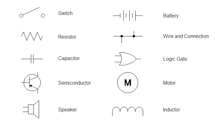
1. Switch: A switch in a wiring diagram controls the flow of power between different components and areas. The symbol can represent different types of switches like the Push button switch, Limit switch, 2-way switch, DPST switch, DPDT switch, SPDT switch, etc.
2. Wires: The wires represent the connections between different components in a circuit. The symbols are then differentiated to represent the joined and not joined wires. While the joined one form two T junctions, the non-joined ones cross on one another.
3. Battery: One or more cells joined together to form a battery. It indicates the power input in a circuit. Batteries are a significant component in electrical circuits.
4. Resistor: The resistors show restriction in the flow of current in a circuit. They are mainly used to divide the voltage. The resistors are often, but the two main categories are the Variable Resistor and Non-Variable Resistor.
5. Capacitor: It is a small device that stores charge. There are two main symbols for this component: one showing a polarized capacitor and the other non-polarized. It is also sometimes paired with a resistor to represent a filter that passes AC signals while blocks the DC.
6. Motor: A motor is a device that converts the electrical power input to kinetic energy.
7. Speaker: By definition, a speaker is a device that converts digital input into analog sound waves. The speakers are primarily used in televisions, mobile phones, computers, etc.
8. Inductor: They are two-terminal electrical components/coils that store energy when placed in a magnetic field. It also has different symbols such as a half inductor, position transmitter inductor, mutual inductor, etc.
9. Logic Gate: They are an important component for storing and outputting the data. Logic Gates take 1 and 0's to convert them into an output depending on their state and case.
10. Semi-Conductor: The symbols for semi-conductors are usually used for representing diodes, rectifiers, controlled switches, Diac, Triac, etc.
How to Read A Wiring Diagram
To read a wiring diagram, you should know different symbols used, such as the main symbols, lines, and the various connections.
Step 1: Recognize Wiring Diagram Symbols
To read a wiring diagram, first, you have to know what fundamental elements are included in a wiring diagram, and which pictorial symbols are used to represent them. The common elements in a wiring diagram are ground, power supply, wire and connection, output devices, switches, resistors, logic gate, lights, etc. A list of electrical symbols and descriptions can be found on the "electrical symbol" page.
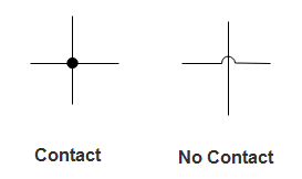
Step 2: Line Junction
A line represents a wire. Wires are used to connect the components. All points along the wire are identical and connected. Wires on some places need to cross each other, but that does not necessarily mean that they connect. A black dot is used to indicate the injunction of two lines. The main lines are represented by L1, L2, and so on. Usually, different colors are used to distinguish the wires. There should be a legend on the wiring diagram to tell you what each color means.
Step 3: Types of Connections
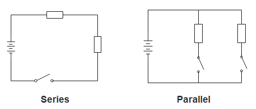
Usually, circuits with more than two components have two basic types of connections: series and parallel. A series circuit is a circuit in which components are connected along a single path, so the current flows through one component to get to the next one.
In a series circuit, voltages add up for all components connected in the circuit, and currents are the same through all components. In a parallel circuit, each device is directly connected to the power source, so each device receives the same voltage. The current in a parallel circuit flows along each parallel branch and re-combines when the branches meet again.
EdrawMax
All-in-One Diagram Software
- Superior file compatibility: Import and export drawings to various file formats, such as Visio
- Cross-platform supported (Windows, Mac, Linux, Web)
How to Draw A Wiring Diagram
How to make a wiring diagram easily? Using EdrawMax to create your own wiring diagram.
Step 1: Open EdrawMax desktop software or EdrawMax web-based application.
Step 2: Navigate to [New]>[Electrical Engineering]>[Basic Electrical]

Step 3: Select one wiring diagram template to edit on it or click the [+] sign to start from scratch. Also, you can use massive wiring design diagram symbols and elements from libraries in left menu to customize your wiring design diagram.
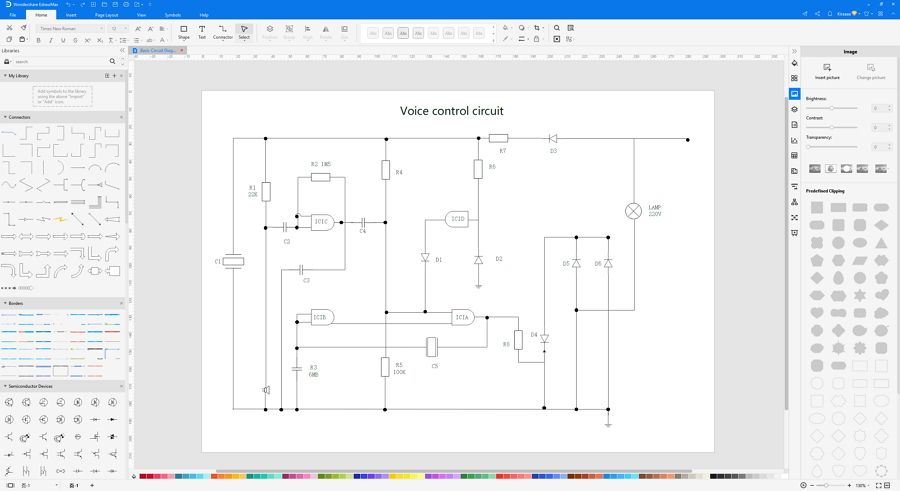
Step 4: Once finished your creation, you can export the file in multiple formats, including Graphics, PDF, editable MS Office file, SVG and Visio vsdx file.

Step 5: Besides, you can share your diagram with others via social media and web page. Or publish your diagram in EdrawMax template gallery to show your work with others.

If you are still confused the steps of how to create a wiring diagram in EdrawMax, here is a video guide to help you understand how to create a professional wiring diagram in detail.
Wiring Diagram Examples
Instead of putting pressure on your brain and drafting a wiring layout, you can easily use EdrawMax’s free templates that help create the most professional diagrams in a minute. With the variety of templates and the massive array of tools and special effects, you can draw wiring diagrams for anything. Let’s have a look at some top wiring layouts.
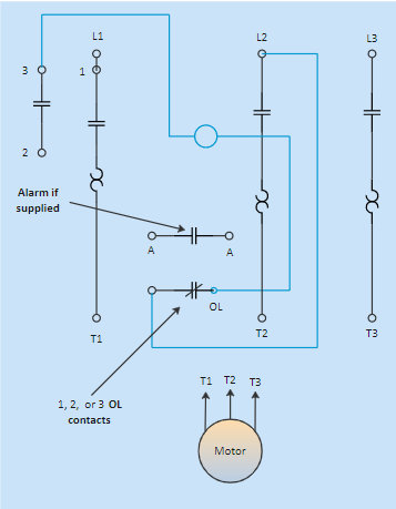
Example 1: Motor Starter Wiring Diagram
This is a simple wiring diagram of a motor starter. It shows the position of the components and the connections between them. The diagram is easy to read and understand and can help guide the controller’s wiring. The arrows and open terminals show the connections used by the people.
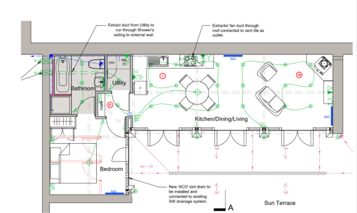
Example 2: Home Electrical Wiring Plan
This diagram shows a detailed electrical wiring plan for a house. It deals with internal and external connections through the walls and ceiling and also caters to other major and minor wiring needs in a house. The plan discusses all the power outlets in detail and how the wires will flow through the house. This electrical wiring layout can be of great help while constructing a building or a house.
Example 3: 3-way Switch Wiring Diagram
A 3-way switch helps control a specific device like a bulb from two different locations in a circuit. The diagram shows how a three-wired cable runs between both of the switches while the two-wire cable runs between the bulb.
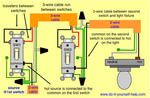
Sourece: do-it-yourself-help.com
Example 4: Harness Wiring Diagram
This harness wiring diagram shows how to match up the wires for each connection to the wiring harnesses.
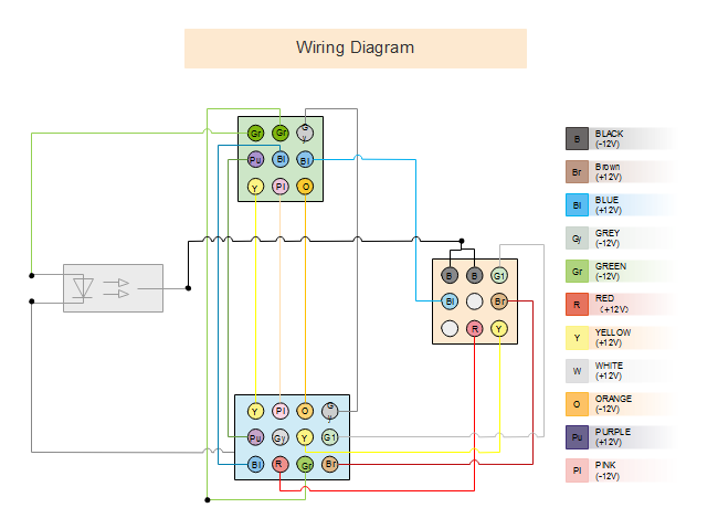
Example 5: Electrical Wiring Diagram
Create an electrical wiring diagram to display wire connections and the physical layout of an electrical system or circuit.
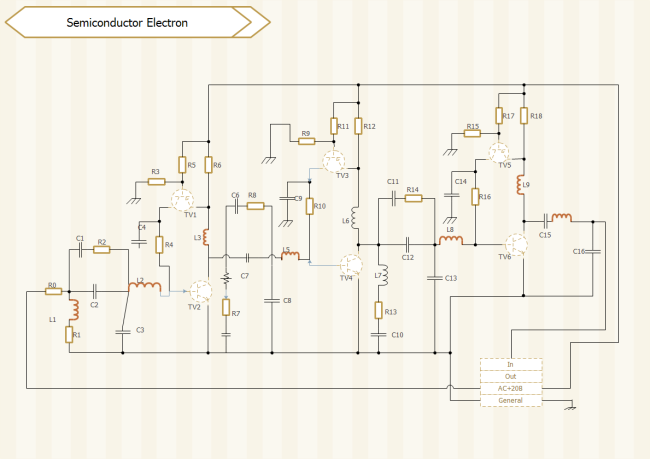
Example 6: Semiconductor Electron Diagram
Semiconductors are used extensively in eletrical circuits and most of them are crystals that are made of silicon.
EdrawMax: Design Thoughtful and Accurate Wiring Diagrams
EdrawMax is a powerful but easy-to-use wiring diagram software that makes it easy to create professional-looking wiring diagrams based on pre-formatted wiring diargams templates and examples - with no drawing required. The smart wiring diagrams symbols are designed with auto generation arrows, allowing users to add and connect shapes easily.
EdrawMax is available for Windows, macOS, and Linux. The tool has several categories for almost all types of industries, and each category further has numerous templates to choose from, thus saving you a lot of time that you would otherwise waste in structuring a diagram, wiring diagram for this example, from scratch.
According to this article, there are mainly four parts to illustrate what is the wiring diagram, to tell you the symbols of wiring diagram design diagram, and to show you how easy and helpful EdrawMax wiring diagram tool is, then shows some wiring diagram templates and examples. Creating a perfect wiring diagram with EdrawMax is an effective way to design.
EdrawMax is an easiest all-in-one diagramming tool, you can create wiring diagrams and any other type diagrams with ease! With substantial wiring diagram symbols and cliparts, making wiring diagrams could be as simple as possible. Also, it supports to export your work in multiple formats and share your work with others. Get started to create your wiring diagrams now!
Expert Tips:
- A good wiring diagram needs to be technically correct and clear to read. Take care of every detail. For example, the diagram should show the correct direction of the positive and negative terminals of each component;
- Use the right symbols. Learn the meanings of the basic circuit symbols and choose the correct ones to use. Some of the symbols have a close look. You need to be able to tell the differences before applying them;
- Draw connecting wires as straight lines. Use a dot to indicate line junction, or use line jumps to indicate cross lines that are not connected;
- Label components such as resistors and capacitors with their values. Make sure the text placement looks clean;
- In general, it is good to put the positive (+) supply at the top, and the negative (-) supply at the bottom, and the logical flow from left to right;
- Try to arrange the placement, reducing wire crossings.