Logical Network Diagram
Contents
A logical network diagram is a pictorial representation of how the computers, printers, fax machines, servers, firewalls, etc., are connected with each other in a physical location. These diagrams tell you how the communication would happen within these devices in a network.
The network diagram is like a blueprint that provides the network, IT administrator, and cybersecurity teams to understand the network and how the information flows in it. It lets them troubleshoot the errors and prevent malicious attacks on a network.
If you are wondering about installing a computer or telecommunication network in your home, office, school, university, etc., you have to select a network diagram. These network diagrams are made using different network topologies. So, you also have to select the network topology for your business.
Logical Network Topology
Logical network topology is also called signal topology. Every LAN has a topology, or the way that the devices on a network are arranged and how they communicate with each other. The way that the workstations are connected to the network through the actual cables that transmit data -- the physical structure of the network -- is called the physical topology. The logical topology, in contrast, is the way that the signals act on the network media, or the way that the data passes through the network from one device to the next without regard to the physical interconnection of the devices.
How Logical Network Diagrams are Useful?
In this section, we will know the benefits of using network diagrams for deploying a network in your offices, educational institutions, hotels, and other industries, etc.
You might have to modify your network or extend it more, or you have to establish a new one from scratch for all of these purposes. You will require a network diagram as it will provide the blueprint of how the information flows on your premises, and you will have the roadmap to track every network component in the network.
Troubleshoot errors
Errors, data leaks, bugs, issues are the worst nightmare for an IT administrator and networking team. But if you have a network diagram deployed on a place you are in charge of, this nightmare can be minimized.
Suppose there is an issue that causes an error and stops the flow of information or data between the computers in a network. In that case, you can easily track it using the network diagram compared to the situation when you don't have any guidance about where to start.
Avoid IT clutter
IT clutter happens when your IT components are disorganized, and everything seems like a mess.
This problem causes you severe loss because suppose if there is an error that took the network's production down, you as a networking guy have to sort out that error, but before this, you have to find the root cause, and for this, your network components should be well-organized.
The network diagram helps you to untie the tight knot of unorganized IT components.
Security and Compliance
The basis of every cyberattack is the unsecured network. Every year, the company loses billions of dollars in the cyberattack. So, you have to secure your network and take all necessary measures to protect it from malicious activity.
These activities help you stay compliant with industry frameworks like NIST, GDPR, CIS, ISO, etc. and save you from these organizations' billion-dollar fines for violating any rule of law. The network diagram lets you organize your network by keeping cybersecurity in mind.
The benefits, as mentioned earlier, are those that should be elaborated. Some more benefits of using network diagrams include.
- It helps you to complete network-related projects.
- Selling your handmade networks in the market.
- Send vendors RFPs by keeping aside the confidential data.
Logical vs. Physical Network Diagram
Logical Network Diagram Symbols
It has defined some commonly used symbols to draw logical network diagrams. Just drag and drop pre-drawn logical network diagram symbols representing computers and network devices.
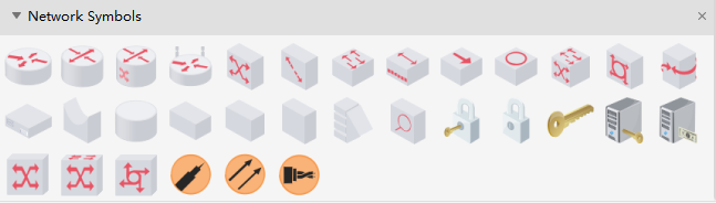
Logical Network Symbols
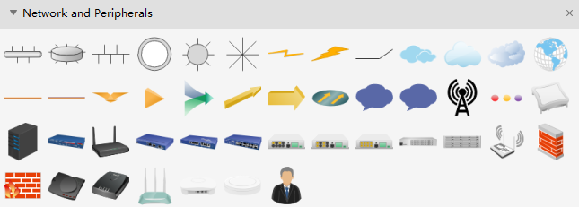
Logical Network Diagram - Network and Peripherals
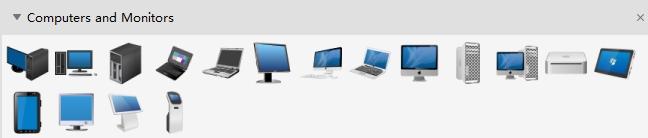
Logical Network Diagram - Computers and Monitors
EdrawMax
All-in-One Diagram Software
- Superior file compatibility: Import and export drawings to various file formats, such as Visio
- Cross-platform supported (Windows, Mac, Linux, Web)
How to Create a Logical Network Diagram?
In this section, you will get an overview of how to make a logical network diagram. It is always a good and compliant practice to consult the networking team to design a logical network diagram for establishing a network, but if you have no access to the team or your project is small, you can follow the below steps.
Gather All the Components
The very first step is to gather all the information and components about the network. List all the components like workstations, mainframes, hubs, servers, routers, firewalls, etc. don't forget to include the IP addresses of every host.
Map Your Diagram
Now when you have gathered all the data and components, map them to make a diagram. You can take help from the internet by picking any logical network diagram template. You can also use computer software that will suffice you in your diagram-making.
Connecting the Devices
In this step, connect each hardware component with a line that will show you how the information flows throughout the network. Know each line that is connected with a device and label it.
Label Shapes
It is a best practice to label the shapes according to their functionality. The best practice is that the symbols should look exactly like what it represents.
Formatting
Now, if you have to present the diagram to the managers or stakeholders, format it so non-technical people can easily understand it.
Logical Network Diagram Examples
This section will see some practical examples of a logical network diagram that will open our minds about what we saw above. You can also take these templates to improve your diagrams.
Example 1: Logistics Network Diagram
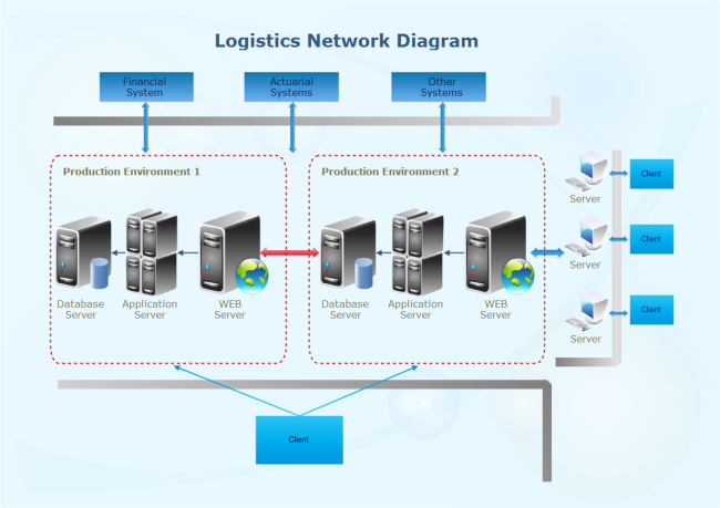
The logical network Diagram will be used to represent how you network connections are using the upper layer of the OSI, and will help to understand your IP addressing.
Logical topologies are bound to the network protocols that direct how the data moves across a network. The Ethernet protocol is a common logical bus topology protocol. LocalTalk is a common logical bus or star topology protocol. IBM's Token Ring is a common logical ring topology protocol.
A network's logical topology is not necessarily the same as its physical topology. For example, twisted pair Ethernet is a logical bus topology in a physical star topology layout. While IBM's Token Ring is a logical ring topology, it is physically set up in a star topology.
Example 2: Data Center Network Diagram
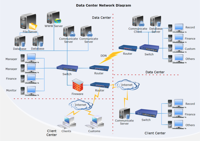
View a data center network diagram template and make the most of it in your own designs. It will surely be of great help. For get more network diagram templates, you can visit Edraw Template Center to find different types of examples that can be customized in Edraw Max.
Example 3: Clear L3 Logical Network Diagram
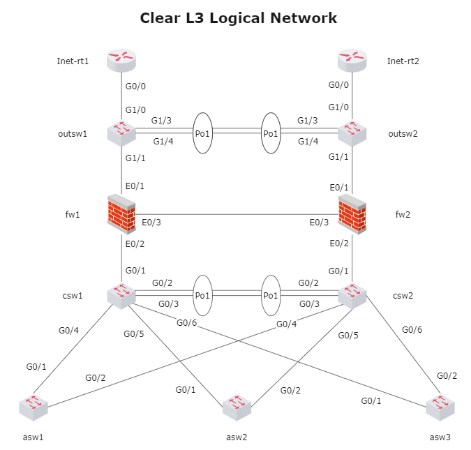
The above illustration is of the logical network diagram. In this diagram, we can see how the information is flowing throughout the network. The lines are mapped to show you this. In this diagram, all the network components are connected with each other. Every network component is marked and labeled to understand what is happening quickly.
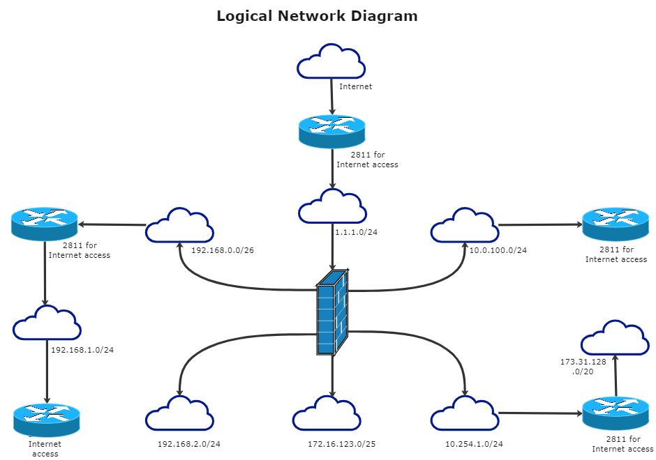
Example 4: Firewall Logical Network Diagram
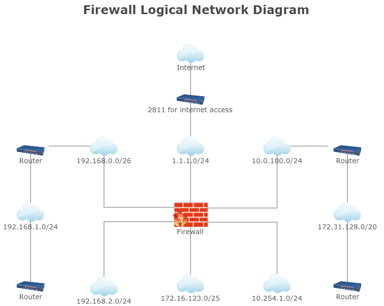
The above illustration is of the firewall logic network diagram. In the above example, the routers are connected with networks that are connected with each other. All the networks are connected with a single firewall in this diagram. And then, all networks and routers are connected with a single router to access the internet.
Example 5: Classroom Setup Logical Network Diagram
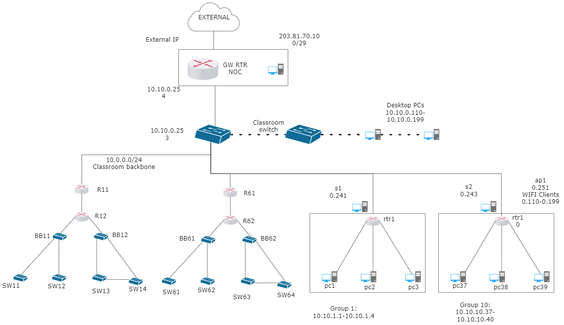
The above illustration is of the school logical network diagram. In this example, multiple switches are connected with a single switch and router to connect with other networks in the schools. All the switches are connected with a single switch to connect to the internet.
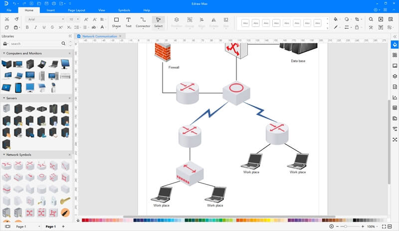
Logical Network Diagram Software
Edraw Network Diagram Software is ideal for network engineers and network designers who need to draw logical network diagrams. You can make a professional network diagram in minutes with EdrawMax !
System Requirements
Works on Windows 2000/2003/2008/Vista/7/8/10 (32bit/64 bit)
Works on Mac OS X 10.10 and later
Works on Linux (Debian, Ubuntu, Fedora, CentOS, OpenSUSE, Mint, Knoppix, RedHat, Gentoo and More)
Supports to design on Web
Software Features
- Vector-based shapes and templates that are pre-designed
- An all-in-one diagram maker that can make over 280 types of diagrams and serve all of your purposes.
- Easy to use with the drag & drop interface, abundant symbol libraries and automatic formatting tools
- Run on common operating systems and work on different devices.
- Seamlessly integrated with MS Programs
- Accompanied by a plethora of well-designed templates and examples and premade symbols
- Export documents into various file formats and has great compatibility.