ER Diagram Symbols and Notations
Are you new to ER Diagrams and need a quick guide regarding the basics? Do not worry; we have it covered. This guide serves to assist you in any queries you may have regarding ER diagram symbols and notations.
Contents
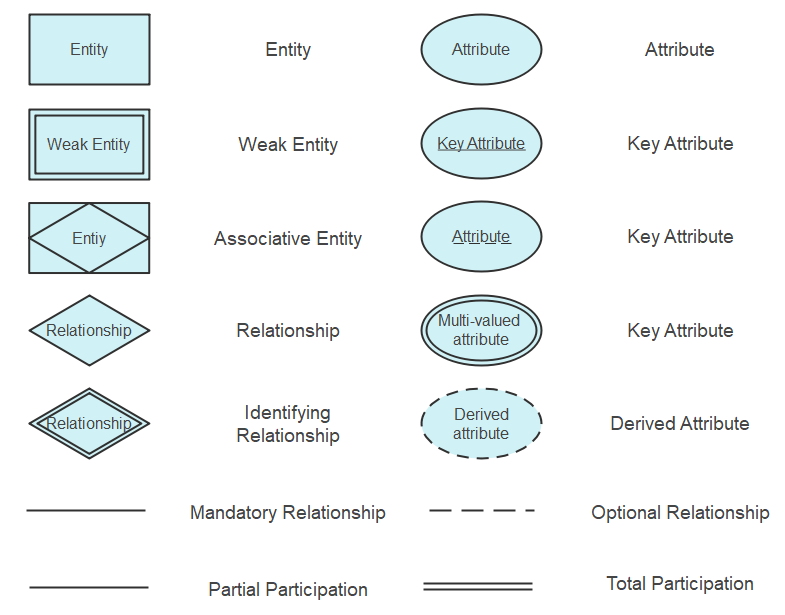
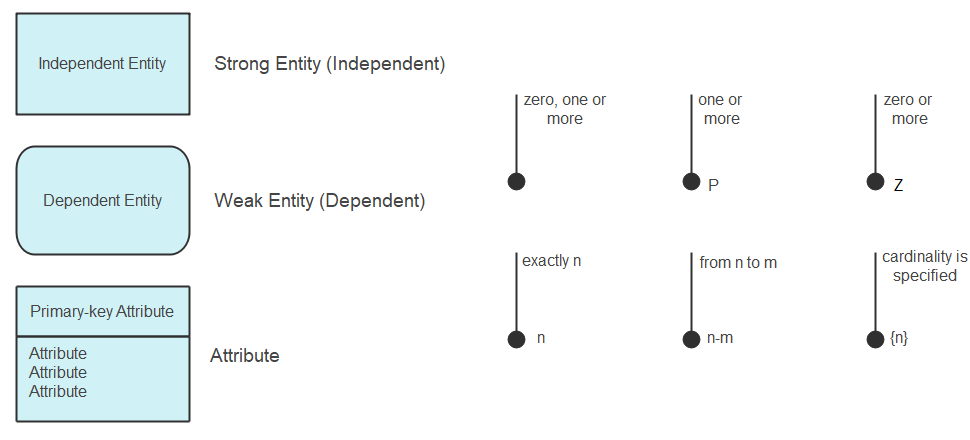
Below are pre-drawn ER diagram symbols in Edraw ER diagram software, including entity, weak entity, strong relationship, weak relationship, attribute, derived attribute, constraint and participation, etc.
There are several ER diagram notations exist and only differ a little. Today, we will be briefly discussing them and their notation styles.
Chen ERD Symbols
Peter Chen was the one responsible for coming up with the Chen ERD notation. He was one of the first individuals who used ERD in database design.
One of the most basic symbols of an ER diagram is the entity. To further elaborate on it, keep reading.
ERD Entity Symbols
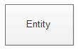
An entity is something that is present in an organization or institute and needs to be represented in the database. They are primarily nouns such as customer, location, concept, event, or person. They are essential for the representation of data. These entities are made of attributes which in turn represent the entity.
Examples of Entities
Location: When shown as an entity, the location can be denoted as Store, Shop, Factory, etc.
Person: The denotation of the person depends on the database being created. If it is for a hospital, this could be a patient, the doctor, or a nurse. If it is a library, then it could be the librarian, students, employees, etc.
Categories of Entity
There are three different types of entities, and we will briefly discuss them along with their symbols.
Strong entities are also referred to as the parent entity as sometimes weak entities can rely on them. They also have primary keys distinguishing them from the other categories.
The second category is the weak entity. They lose their meaning if a parent entity does not exist and they have no primary key.
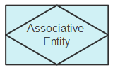
They tend to associate several entity types together depending on the several instances. They are also known to contain the attributes for the relationship between those entity types.
What is an Entity Set?
An entity set, in simpler terms, is a group of similar entities. They may either share similar values and have attributes of the exact nature.
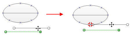
Some people may be confused about how to use a connector to connect entity symbols. Actually, it is easy. You can move the connector towards the shape, then you can find that the entity shape has lots of green marks. When the red mark appears, it means the two have connected.
ERD Attribute Symbols
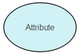
The attribute symbol is also the second step in making an ER diagram. It is an essential component of the entire process.
An attribute is a characteristic related to the entity. These characteristics are used to understand the database in more detail and depth.
Examples of Attributes
Student: To understand it better, an entity can be a student. The attributes for the student would be name, class, student ID. These describe the type of data collected regarding the student.
Class: Now a class might have the attributes such as subject, time, place, duration, and capacity. These would describe the class.
Categories of Attributes
Just like entities, attributes are also divided into different categories. They are as follows.
Simple attributes can also represent only one value. They can either show a relation of one-to-many or many-to-many.
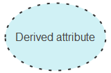
These attributes, at times, do not exist in the database, but their values can be derived from the preexisting attributes. Things such as age, work experience, and academic tenures can be derived from quantified attributes.
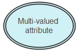
Multivalued attributes, as the name suggests, can have more than one value. An example of such attributes would be emails, phone numbers, etc.
ERD Relationship Symbols
A relationship is the formation of an association between two entities. Verbs or verb phrases mostly show these.
Examples of Relationships
If one entity is a student and the second is a class. The relationship between them would be “studying.” As the student studies in the class.
Categories of Relationships
The relationship also has different categories to show the strength of the association between two entities. The categories are as follows.
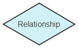
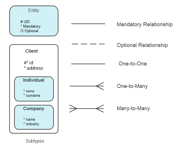
A strong relationship shows a direct link between two entities.
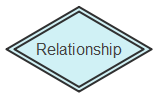
A weak relationship is between a weak entity and the parent entity.
Crow's Foot Notations
Gordon Everest was the creator of the Crow's Foot notation in an article he wrote in 1976 for the Fifth Computing Conference. The basic idea was to use the name inverted arrow notation, but Gordon stuck with the Crow’s foot notation. The symbols used for this notation are:
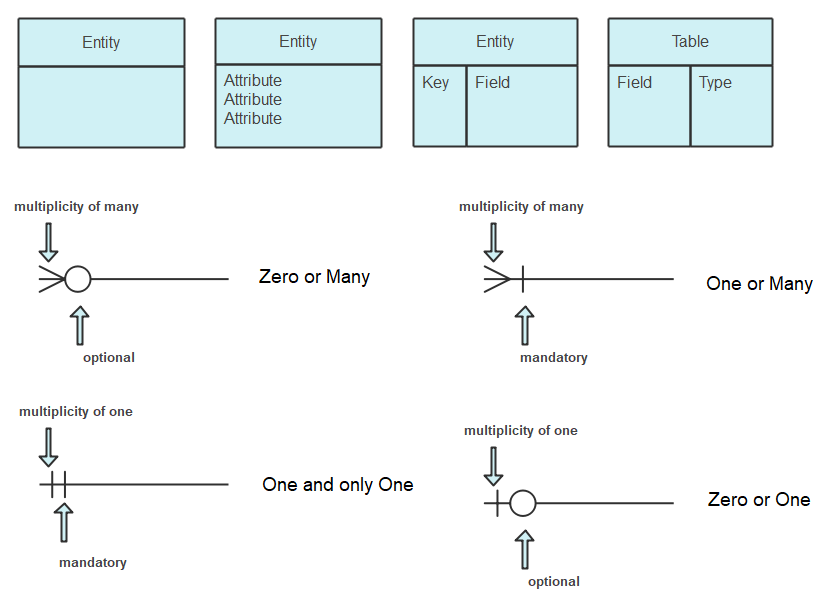
ERD Table Symbols
A table is another way of representing entities. They are an essential component of physical ER diagrams. The table consists of the entity, and the different attributes related to it are listed right below it. They are also called fields in the physical ER diagram.
What are Keys?
Keys are used to categorize different attributes. The purpose of tables is to make the ER diagram more organized and efficient. The keys serve to link tables with one another in a database. There are two types of keys.
Primary keys are attributes that are unique to a table and only identify with one entity.
Foreign Keys are created when an attribute links with another entity in a one-to-one or one-to-many relationship.
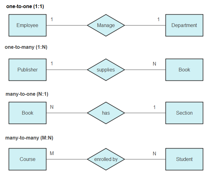
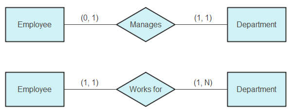
ERD Cardinality
Cardinality is the maximum times an entity can relate to an instance with another entity or entity set. Ordinality is the minimum time an entity can relate to an instance with another entity or entity set. Usually, in ER diagrams, these terms are used under cardinality itself.
The cardinality constraints are within the maximum and minimum numbers that are relevant to a relationship.
Cardinality is represented by lines that have different stylings depending on the type of cardinality that is to be shown.
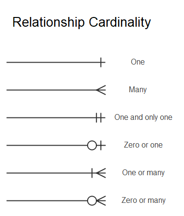
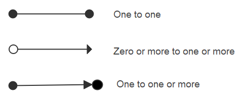
- One to One: In such a case, the origin entity has a one-to-one association with the other entity. This is also an example of a one-to-one relationship.
- Many: In this category, the target entity can be related many times by the origin entity. This also shows a one-to-many relationship.
- One and Only One: In this cardinality notation, the origin entity has only one entity linked with the other entity.
- One or Many: In this scenario, the origin can have one or many linked entities with the other entity set.
UML Notation
UML is well known for documenting, visualizing, and specifying the components of non-software and software systems. Since the UML has many diagrams, it is divided into two representing the behavior and the other structural information.
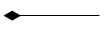
It was named the composition association relationship in UML 1.4, represents whole-part relationships and is a form of aggregation. A composition relationship specifies that the lifetime of the part classifier is dependent on the lifetime of the whole classifier.
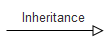
It helps people to communicate structure and inheritance of an object model. Inheritance relationships organize classes into generalization-specialization (superclass-subclass) hierarchies; they provide a basic re-use mechanism for sharing attributes and operations.
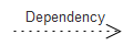
It is a relationship in which one element, the client, uses or depends on another element, the supplier.
It is a relationship between two classifiers, such as classes or use cases, that describes the reasons for the relationship and the rules that govern the relationship.
Other Types of ERD Notations
1) Barker’s Notation
UML is well known for documenting, visualizing, and specifying the components of non-software and software systems. Since the UML has many diagrams, it is divided into two representing the behavior and the other structural information.
2) Bachman Notation
Charles Bachman was responsible for the creation of this notation. He was a computer scientist and developed the Chen notation to make another set of notations. He was also one of the database pioneers.
The notations are as follows.
3) IDEF1X Notation
It is known as the Integration definition for Information Modelling. In the 1970s, the US Air Force required semantic data models. This gave rise to ICAM programs that later developed into IDEF1X. This used syntax to create relational databases.
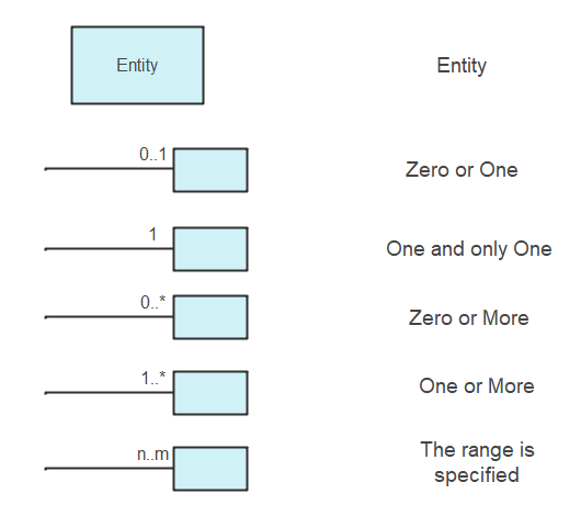
4) Min-Max Notation/ISO Notation
Jean Raymond Abrial introduced the Min-Max Notation in 1974. He brought this to challenge the limitations the Chen notation had of the minimum and maximum. This is also part of the semantic database models.
These are the several other ER Notations and symbols that are used.
Object Relationship Symbols
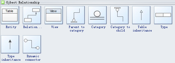
The following picture is the object relationship symbols including entity, relationship, view, parent to category, category to child, table inheritance, type, type inheritance and dynamic connector.
Type of a relationship is created depends upon how related objects are defined.
Type inheritance is an additional property offered by hierarchy within structured complex data.
Express-G Symbols
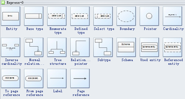
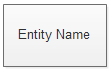
Entity in a database could be a single person, a place, or a thing about which data can be stored.

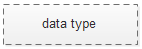
Defined type is the most important datatype in Express-G.
Select type defines a choice or an alternative between different options. Most commonly used are selects between different entity types.

Tree structure is a structure in which there are successive branchings or subdivisions.
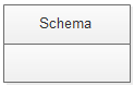
Schema is a way to logically group objects such as tables, views, stored procedures, etc.

Page reference is a reference to an instantiation of a page.
Martin ERD Symbols
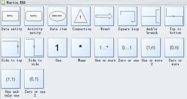
Data entity is an object, event, or phenomenon about which data is stored in a database.
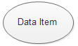
Data item is a unit of data contained in a record, describing a particular attribute, and it requires one or several bits, bytes, or words to represent an entity.

Connection is the setting up of resources so that a particular object such as a database or file can be read or written to.

Events with different colors represent different events.
ORM Diagram Symbols
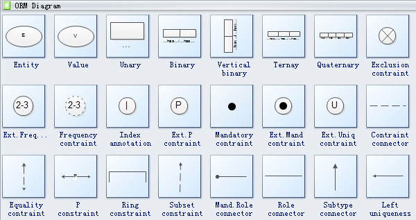
Entity in a database could be a single person, a place, or a thing about which data can be stored.

Unary means consisting of or involving a single component or element.

Ternary means "composed of three items".

Index annotation defines an index for the class as a whole (typically a composite index).
You can watch the video tutorial below and learn more details about how to draw an ER diagram with EdrawMax!
Use EdrawMax for ER Diagram Creation
Extensive pre-drawn ER diagram symbols are provided with vector format, including entity, user, relationship, attribute, aggregation, line connector, etc. Customizable and with high quality, these symbols will help you make professional ER diagrams in a few minutes.
When you need to create an ER diagram to document a database, it will be much easier using pre-made symbols and icons. This page gathers many useful symbols that often used in ER diagrams, Chen ERD, Express-G diagram, ORM diagram, Martin ERD and database model diagram.
ER diagrams are best created with the use of proper and powerful diagram tools. One such tool is EdrawMax which is highly effective and one of the best tools for creating ER Diagrams.
So, it is time to download it and use its completely free features to get your work done!!