Knowledge

Block Diagram of Computer - Tutorial and Examples

Know it All about Block Diagram of Computer

Block Diagram of a Computer and Its Component

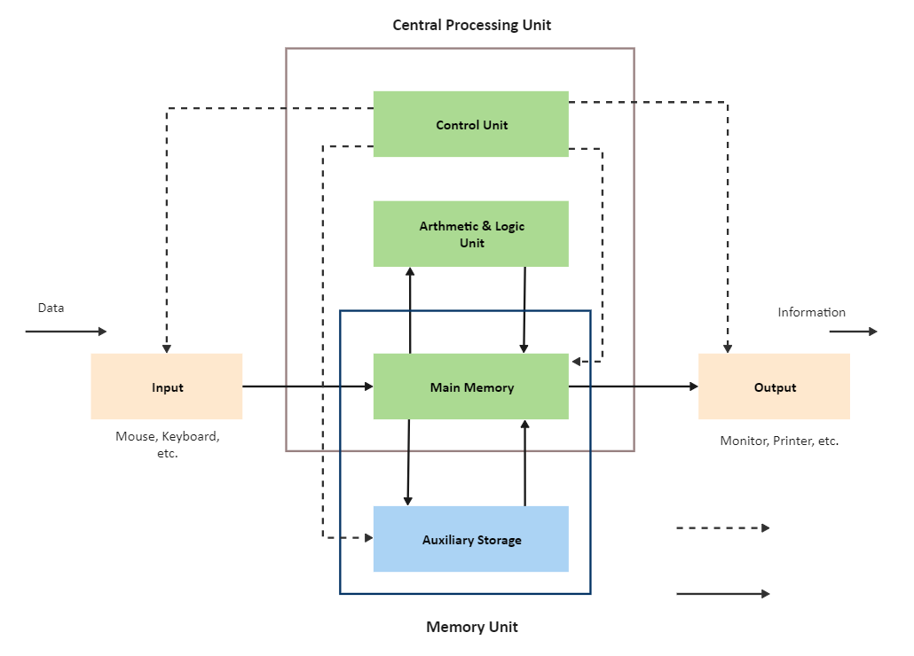
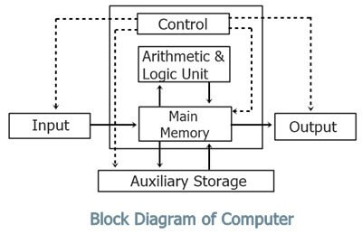
The diagram that illustrates the primary components of the computer system is known as the block diagram of the computer. The basic definition of the computer system is that it takes some data then it processes it and then it produces the final outcome and this is what the block diagram shows.

Block Diagram of a Computer

The main components of the computer system are the Central Processing Unit (CPU). The Central Processing Unit consists of two more parts the Arithmetic and Logical Unit(ALU), and the Control Unit(CU). For processing the data to give output, the computer needs some space to keep the data there and from here the Storage Unit takes the lead. The components are briefly described below.

The Input Unit

The input unit is the platform from where the raw data is passed into the computer system. The input can be in any form. For example, the mouse-clicked input, button-input, keyboard-input, etc. All the input data is passed from the input unit to the computer’s storage unit.

input devices

Central Processing Unit (CPU)

The CPU is the primary component that processes the input passed into the computer. It is also called the heart or brain of the computer without the CPU you just have the useless desktop. The CPU has two components Arithmetic Logical Unit (ALU) and Control Unit (CU).

cpu

cpu

EdrawMax

All-in-One Diagram Software
Create more than 280 types of diagrams effortlessly
Start diagramming with various templates and symbols easily
  • Superior file compatibility: Import and export drawings to various file formats, such as Visio
  • Cross-platform supported (Windows, Mac, Linux, Web)
Security Verified | Switch to Mac >>
Security Verified | Switch to Linux >>
Security Verified | Switch to Windows >>

Arithmetic Logical Unit (ALU)

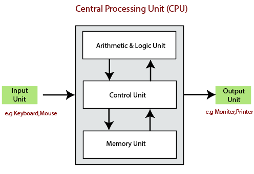
We all know that computer understands the language of the binary numbers that is 0 and the 1. The Arithmetic Logical Unit (ALU) is the digital circuit that takes these 0s and 1s and performs the necessary arithmetic operations on it and releases the results as the output asynchronously.

Control Unit

The Control Unit (CU) is like the traffic guy. It controls the instructions flowing in and out of the CPU. The CU is smart enough to sense that when the CPU’s central processor needs data and when not. If the data is required then it retrieves it from the Storage Unit and transfers it into the CPU. The CU converts the data into signals and passes it into the central processor.

Storage Unit - Primary and the Secondary Unit

The raw data from the Input unit is saved in the Storage Unit. It is the place where the data that is to be processed and processed data is stored. The Storage Unit is further classified into two parts.

  • Primary Storage
  • Secondary Storage

Primary Storage

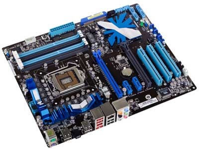
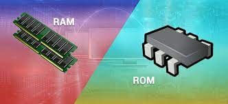
This storage is also known as the main memory of the computer system. This part of the storage unit holds the data, programs, and instructions that are currently in use. This storage part resides in the motherboard. Primary storage contains the ROM and RAM of the computer system.

Primary Storage

Secondary Storage

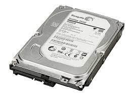
It is a non-volatile and permanent data storage device. It is the place where the data is stored for a short or a long time. The secondary storage supports the primary storage. This device is also known as the hard drive of the computer. It is primarily used as a backup device.

Secondary Storage

Output Unit

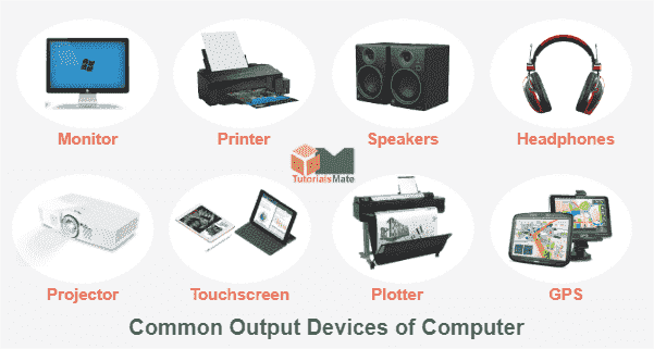
The output unit is the place through which the computer system outputs the data. The output unit is always hardware. The computer screen, speakers, printer, etc. are the output devices because from these devices users get their processed data.

Output Unit

Source: www.tutorialandexample.com

How Does the Computer Complete an Instruction Block by Block?

For the step-by-step understanding of how the computer processes the information and outputs it, we have to see the block diagram of the computer system.

In the following way, the computer processes the information.

  • In the input unit, the user’s data is passed, then it is converted into the machine-readable form, and then this data is stored in the computer’s memory unit.
  • From the memory, this data is passed to the CPU of the computer system, and in the CPU the ALU does all the necessary arithmetic operations on it with the central processor.
  • Now, the processed data is stored in the computer’s main memory and then the memory will decide when to output this data.
  • From the main memory, this data is passed to the output unit of the computer system and the user gets it.
  • All this traveling of data throughout the whole computer system is controlled by the Control Unit of the CPU.

How to Draw the Block Diagram of Computer System?

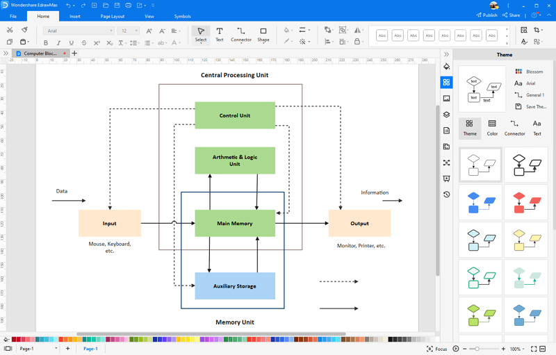
Every person who is studying computer science or is a professional computer scientist should know and how to draw the block diagram of the computer system in this section, we will draw the block diagram of the computer system by hand and by computer software.

Drawing by hands

Get the paper and pencil and start the work.

  • First, draw the large and broad rectangle in the vertical form.
  • Make three boxes inside the main rectangle figure, and name them as the Control Unit on the above box, the Arithmetic Logical Unit on the box in between, and the main memory on the box below.
  • Below the main rectangle box, you can draw a small box for auxiliary storage, but it is not necessary.
  • Make the box for the input unit on the left side of the main rectangle box.
  • Connect the control unit to the input unit, the output unit, auxiliary unit, and main memory with the dotted line, and the direction should be towards the units just mentioned.
  • Now, connect the auxiliary storage to the main memory with the bold line going in and coming out from the main memory.
  • Connect the input unit to the main memory with the bold line directed toward the main memory. Connect main memory to the output unit with the bold line and direction should be towards the output unit.
  • Connect the main memory with the ALU with the bold line as the information is going in and coming out of the ALU.

Your final result should look like this.

block diagram of computer

Drawing with the EdrawMax Software

Follow these steps:

  • Download and install EdrawMax or visit EdrawMax Online to use immediately
  • Search the block diagram templates in EdrawMax Template Community and use the pre-design template without starting from scratch. Alternatively, you can open a blank drawing page and draw with in-built symbols.
  • Block Diagram of Computer System Template

  • On the left side, there is a library vertical bar from there drag and drop the block shape onto the main project. You can use the green selection handles to tailor the size and shape of the box.
  • Double-click on the box to write in it and again drag and drop the three more boxes inside the main box by following the second step.
  • Use the connector option on the above bar to connect the boxes, the connector provides you all kinds of lines, dotted and bold both.
  • Put the connector line to the box from where you want to direct toward the other box and then simply drag the line towards the box.
  • Click on the distribute option, and choose how would you specify the particular block of the diagram by color or patterns.
  • Choose either you want to save or export your final result as a PDF, PNG, JPG, Visio, Word, Excel or PowerPoint file.

Block Diagram of Computer System in EdrawMax

Related Articles