Complete Guide to Architecture Diagrams
Part 1: Architecture and Architecture Diagram
1.1 What is Architecture?
Architecture is nothing but an abstract description of entities in a system. It defines the relations between them and involves a series of decision-making processes.The architecture is a vision and a structure.A system architecture diagram is the distribution of the functional correspondences. These are formal elements, the embodiment of concepts and information.Architecture defines the relations between elements, amongst features, and the surrounding elements.Creating an Architecture diagram is not easy. The examples aim to make things easy for people to understand.
1.2 What is an architecture diagram?
An architecture diagram is a diagram that depicts a system that people use to abstract the software system's overall outline and build constraints, relations, and boundaries between components. It provides a complete view of the physical deployment of the evolution roadmap of the software system.
Part 2: The Functions of an Architecture Diagram
2.1 What are the functions of an architecture diagram?
A diagram is similar to a picture. The architecture diagram examples serve various functions. It always helps the relevant users to learn about system architecture and apply it in the decision-making procedures. It is crucial to communicate information regarding architecture. However, people must follow specific steps before making a diagram for architecture. These are:
- Breaking down communication barriers
- Reaching a consensus
- Decreasing ambiguity
2.2 How can architecture diagrams help you?
An architecture diagram:
a) Help in making the comprehension process easy
With the help of such diagrams, complex information becomes easy to understand in a single image. Viewers can see the ways things interact. People can also witness the downstream effects.
It makes layers in the place of complex systems.
b) The diagrams help improve collaboration and communication
Consistency is one of the poignant problems that software engineers come across. Several discrepancies and miscommunication may take place between the developers and project teams. The diagrams must follow accuracy, standardization, and detail.
Part 3: Types of architecture diagrams
1. System Architecture Diagram
It focuses on the structure along with the technological requirements, external services, servers, and databases.
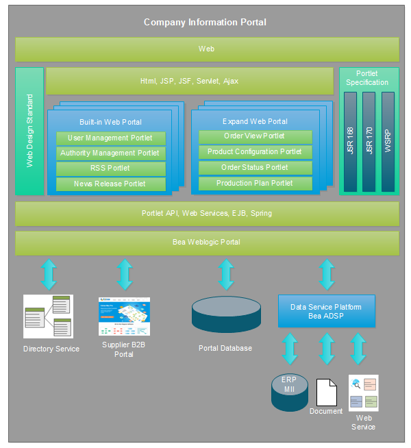
Example 2: Website System Architecture Diagram
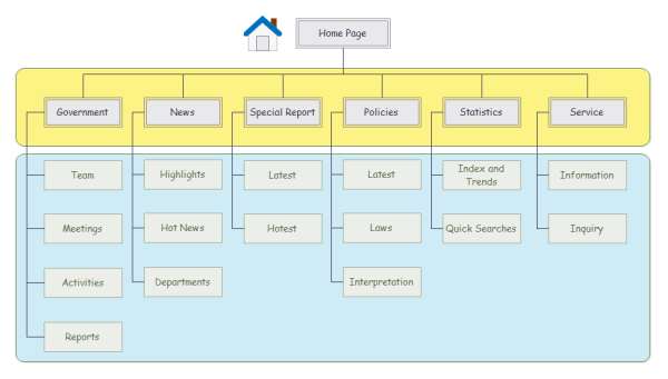
2. Website Architecture Diagram
This diagram helps in website planning and design, including artistic, technological, and practical considerations. It uses a hierarchy structure to show website content management and website directory structure.
Example 1: Website Information Architecture Diagram
Example 2: Website Functional Hierarchy Architecture
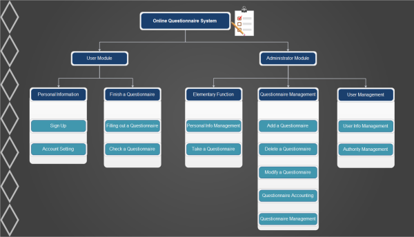
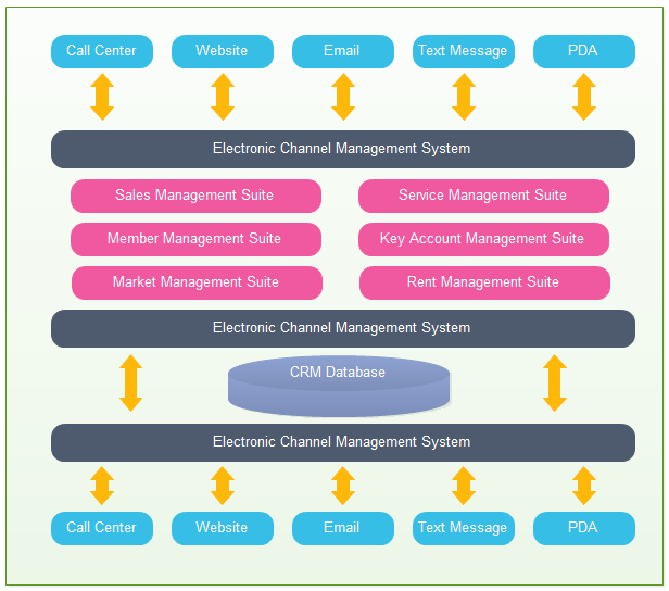
3. Application Architecture Diagram
This kind of diagram involves a plan, system, and processes. It has a functional application as the framework for system procedures.
Example: CRM Application Architecture Diagram
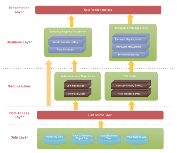
4. Software Architecture Diagram
The physical view is about cartography. It draws the map for physical hardware and system software.
The system components are bound to a group of computable physical nodes.
The physical view helps a software architecture diagram and includes the service layer, business layer, and data layer. It establishes relations amongst both internal and external systems, users, and services.
Example: Flood Control Software Architecture Diagram
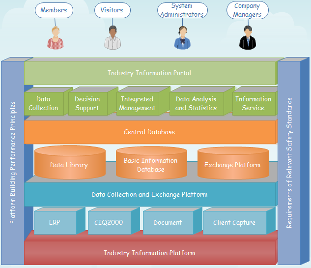
5. Enterprise Architecture Diagram
The Enterprise architecture diagram help manage the business and organizational model of a project. The diagram shows security policies, management tools, business plans, teams, roles, interaction, and workflow.
Example: Projects Enterprise Architecture Diagram

Types Of Views
The most popular amongst them is the 4=1 view.
- The logical view is about the component constraints, component relations, and boundaries after the system software system breaks down.
- The scenario view depicts the functional use cases and system participants. It reflects the interaction system design and the final requirements too.
- The development view describes the system modules' composition and division. More so, it refines the internal packages' composition system. Developers often use this type of statement to reflect the implementation process and system development.
Another one is the process view. It showcases the data input, data output, and communication sequence between the system software components. Also, it reflects the system data and functional flow. Developers can take the help of flowcharts to make such views.
Part 4: Architecture Diagram Symbols
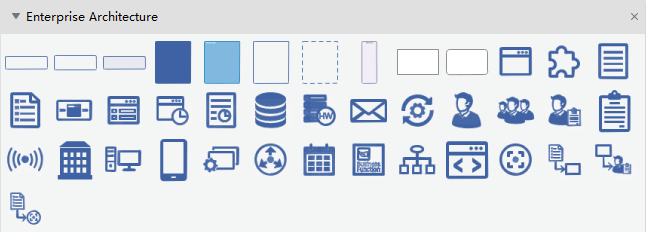
There are numerous symbols for an architecture diagram. These are the program, database, business flow, role association, business flow, impact, goal, component, system, and form.
People can browse EdrawMax and get such symbols there. It offers 100 plus graphical representations and diagrams. There is more than one reason; people should choose this platform. They are:
- Compatibility across platforms
- Offers 100% security of privacy
- User interface and template options
Part 5: How to Create an Architecture Diagram
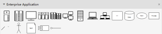
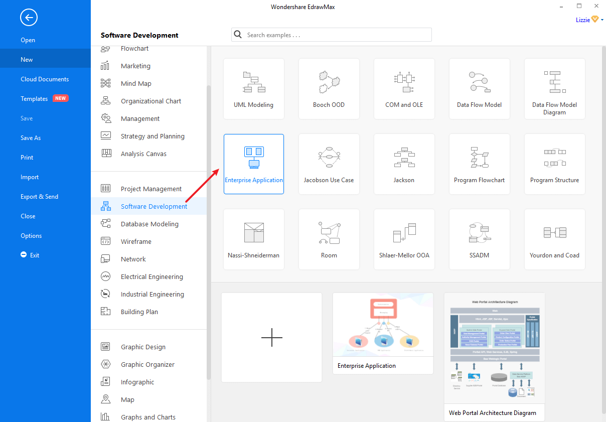
Step 1: Launch EdrawMax on your computer. Navigate to [Software Development] > [Enterprise Application], and you can open a template or a blank drawing page.
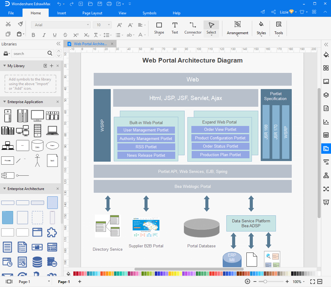
Step 2: As you enter into the workspace of EdrawMax, drag the symbol that you need and drop it onto the canvas. If you need additional symbols, you can search them in the left symbol library. There are also plenty of editing and formatting tools that you can use to modify and style the diagram.
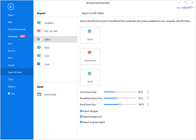
Step 3: When your architecture diagram is complete, you can export it to JPG, PNG, SVG, PDF, Microsoft Word, Excel, PowerPoint, Visio, HTML with just a single click. So you can share your drawings with people who don't use EdrawMax with no need to looking for ways of converting file formats.
Watch the following video to learn to create an enterprise architecture diagram in simple steps!
Part 6: Tips for Drawing Architecture Diagrams
Below are some of the tips for convenience for the architecture diagram developers.
- Documenting the shapes is required. The figures may vary, and one needs to demonstrate consistently.
- Documentation of the edges is mandatory. One can incorporate a dashed, dotted, or straight edge.
- One needs to be mindful of keeping the arrows consistent. They mark data flow and dependency.
- Using colors sparingly could be helpful. One can use colors to emphasize a portion.
- One may use multiple diagrams if necessary. They help to understand different viewpoints.
- Developers can go for merging incomplete diagrams when they represent the same system.
- The inclusion of keys, legends, and glossaries is helpful for better comprehension.
- One can make it eye-catching by using diagramming software. The keys help minimize risks, cut down on admin, and develop traceability.
Also, people need to pay attention to missing elements, or isolated entities, if any. Unexplained acronyms are challenging to comprehend. Nobody should use generic or vague terms as far as possible.
Remember that infusing the diagrams with too much information, assumptions, scripting languages, framework, and complex technologies make things tricky.
Part 7: Conclusion
Proper documentation is mandatory. Only the exemplary diagrams help make things easy.
The architecture diagrams help the stakeholders navigate the projects. More so, they bring clarity across the board. Cloud-based diagramming software is there to help create such graphs. These are available and accessible to everyone. The diagrams are not out-dated. By simply editing the infrastructure in EdrawMax, people can fulfill their requirements in no time.